Low-Cost LiDAR Lens Autofocus System for Cinema Cameras

The author, Nolan Juneau
In the motion picture industry, one of a cinematographer’s jobs is to move the plane of focus of the camera’s lens to line up with a subject so that it is sharp and “in focus.” This job is usually fulfilled manually by an assistant cameraperson (or “focus puller”), but sometimes manual focus pulling is impractical. This is especially true for extremely technical shots on high-end shoots or for lower-budget shoots that cannot afford extra crew members. In recent years, systems have been created to pull focus automatically, but many of the technologies that exist for cinema equipment are either limited in functionality or prohibitively expensive. This brings up a question: Can an effective cinema autofocus system be created that is within reach of lower-budget filmmakers? With funding from a Summer Undergraduate Research Fellowship (SURF) at the University of New Hampshire (UNH), I put this question to the test by designing an autofocusing system that is accurate, fast, and inexpensive, and can be used by filmmakers of any budget level on any camera system.
This project evolved out of the combination of my studies as an electrical engineering student and my professional and personal interests. Much of my life outside of academia is spent around filmmaking: Understanding film theory through watching films and working on my own film projects (specifically in the art of cinematography) is deeply rooted in my DNA. Nearly all cinema cameras and lenses currently on the market, from budget-level to professional-level, do not have in-built autofocusing systems, instead relying on a camera assistant. While this works for most situations, being a solo camera operator on a low-budget film shoot and juggling all the tasks of an entire camera crew often means that accurate focus can be difficult to achieve manually. Thus, I wished to create an autofocusing product using inexpensive modern electronics that is fully functional while costing less than $100 per unit. My prior experience in several aspects of electromechanical design, including computer-aided design (CAD) modeling, soldering, and microcontroller programming, allowed this idea to become a reality.
Methods
Light detection and ranging technology, or LiDAR for short, is a type of distance ranging technology that uses the reflection of light to gauge distances. LiDAR sensors send out pulses of infrared laser light and, using a separate light detector, measure the time between when a laser pulse was sent and when the reflection was received. It uses that data to very accurately calculate the distance between the sensor and the object it is pointed at. Due to the proliferation of inexpensive LiDAR technology over the past decade, an autofocus system can be designed that is much more affordable than others on the market while retaining the precise distance measuring of LiDAR technology. Throughout my research process, the goal was to create a functional proof-of-concept design that would employ LiDAR technology and adhere to the following specifications:
- Allow for autofocus capability for all lenses with a manual focus ring
- Be a self-contained unit that can be easily attached to a cinema camera rig no larger than 150mm x 150mm x 75mm
- Be powered entirely by USB power for ease of portability
Total material cost of the system of no more than $100

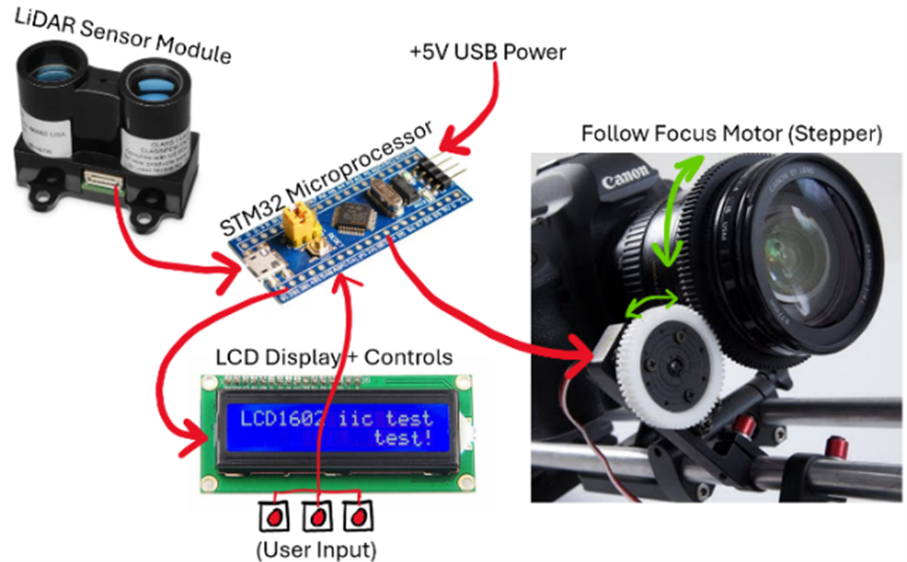
Figure 1: Initial “proof-of-concept” system diagram. Note that the final MCU unit chosen was an Arduino Nano, not an STM32.
The design concept I developed in my SURF project proposal dictated that the basic structure of the system would be separated into three parts. The first of these is a main “control box” that contains a microcontroller (a small, programmable computer that will control all the electronic aspects of the system), an LCD screen to access the settings and controls of the system’s software, and buttons to control the menu of the LCD screen (see Figure 1). The second component is a “sensor block,” which is a 3D-printed assembly that allows the LiDAR sensor to be positioned and locked on the same plane as the front of the lens for accurate distance sensing (see Figure 1). The final component is the “focus motor” system, driven by a stepper motor, which is a type of electric motor that rotates in individual “steps,” allowing for very precise control of the motor’s position. This type of motor requires a separate “driver board,” which converts movement commands from the microcontroller into the voltages required to run the motor. This motor is attached to a 3D-printed gearing system that can move the manual focus ring of any lens with a geared ring (see Figure 1).

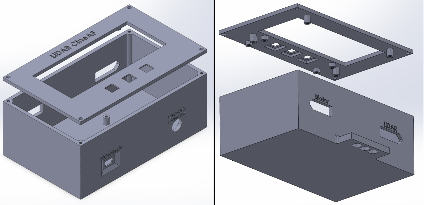
Figure 2: Finalized CAD model of control box: front and back.
My first step was to research and purchase all the core electronics that I would need to start working on the system. I had already planned the general electronic layout in the project proposal (including the microcontroller, motor, LiDAR sensor, and LCD screen), but I settled on my final components to match the project requirements for materials cost, size, and sensor requirements. From there, I used a breadboard to set up all the electronic components. A breadboard is a rectangular plastic board with a grid of holes that allows you to make electronic connections without soldering, allowing for easier prototyping. I then developed the microcontroller software from the ground up to take in the centimeter distance data from the LiDAR sensor module and convert it to a physical position on the focus gear motor, depending on the motor positions at each of the calibration distances. Once the code was near completion, I started work on the CAD designs for the hardware components, including the housing for the control box and the mounting hardware for the focus motor (see Figure 2).

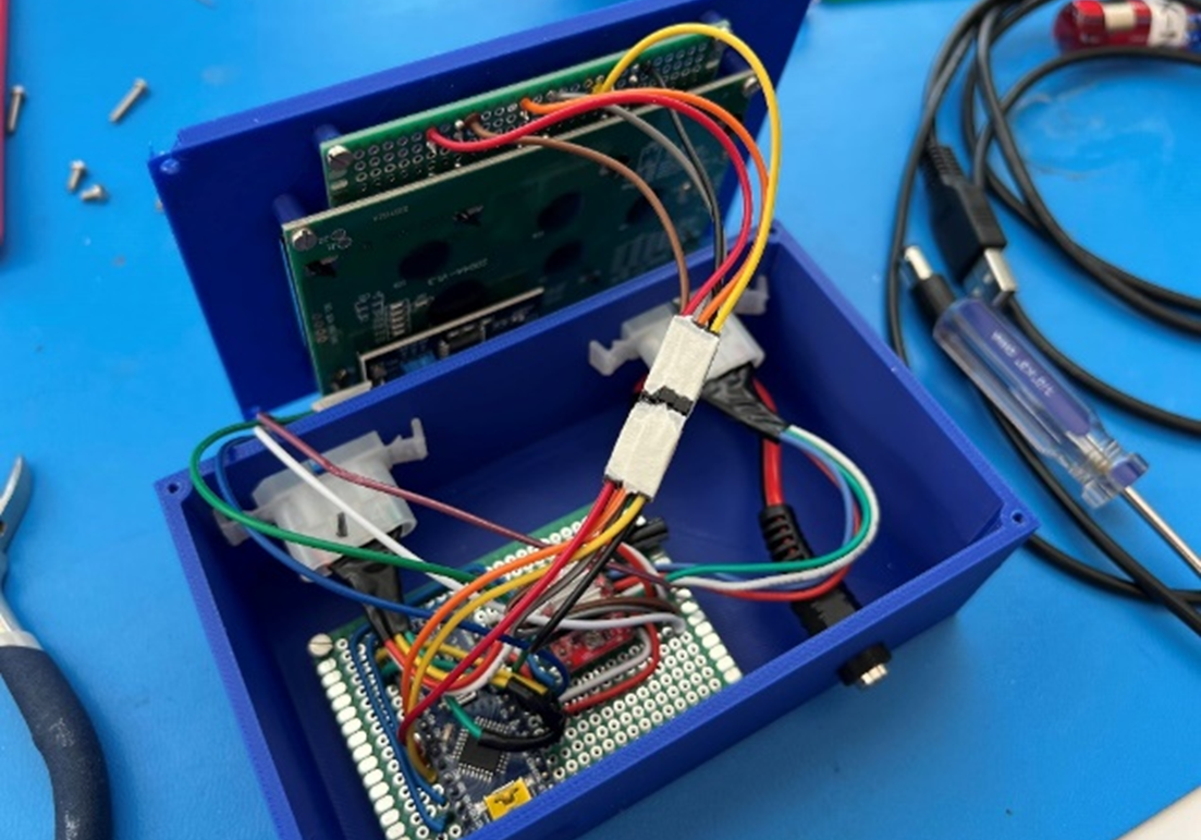
Figure 3: Finished electronics inside the 3D-printed control box.
Because I needed to design these components myself, my process involved designing the CAD models, 3D-printing the parts, and adjusting the CAD models as needed until the parts could be assembled seamlessly. During this time, I also developed the power supply system for the autofocus system—settling on a system that requires two power supplies to run (one for the microcontroller and all in-built electronics, the other for driving the motor). I chose this design because of the different requirements in voltage/current (the electronics require 5V USB power, and the motor requires a 12V high-current supply). Once the main housing parts were finalized, I soldered the electronics onto a blank circuit board (known as a prototyping board) and tested the system to evaluate strengths and weaknesses for documentation and future revisions (see Figure 3).
System Overview
The system that I finalized by the end of the ten-week SURF period consists of the same three “components” as mentioned before: the main control box, the sensor block, and the focus motor system. The control box, housed in a 130mm x 80mm x 50mm 3D-printed housing, contains an Arduino Nano, which is the microcontroller board that acts as the brain of the system; an A4988 stepper motor driver board; a 4x20 LCD display connecting through the I2C protocol (a standardized two-wire communication protocol used for many hardware peripherals and natively supported by the Arduino Nano); and three push buttons for software control (see Figure 3).

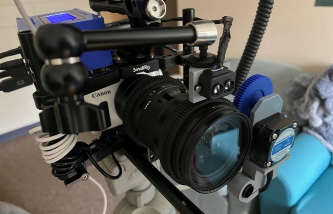
Figure 4: Full LiDAR-AF system attached to a cinema camera rig.
The control box also contains two detachable connectors that are used to connect the sensor block and focus motor systems, and two separate power inputs that can be run off any standard USB-A power supplies (including USB battery banks) (see Figure 4). The sensor block is built from a Benewake TF-Luna LiDAR distance sensor, which is connected via the UART serial connection protocol (a similar two-wire communication protocol to I2C, also supported by the Arduino Nano), allowing for effective communication between the LiDAR sensor and the microcontroller (see Figure 4). The motor system is built from a low-profile stepper motor with a high input current rating to allow for adequate torque to turn the focus ring of a lens while being efficient enough to retain a long battery life (see Figure 4).
Once the system is powered on, the motor gear is attached, and the sensor block has been lined up with the camera lens, the Arduino software prompts the user to calibrate a specific lens. The control buttons are used to set the lens’s focus distance at exactly infinity focus, 3 meters, 1 meter, 0.6 meters, and at the minimum focus value between 0 and 0.6 meters. This calibration process is done by using the distance markings notated on a lens’ focus ring, or by measuring the distance to an object at each calibration point.

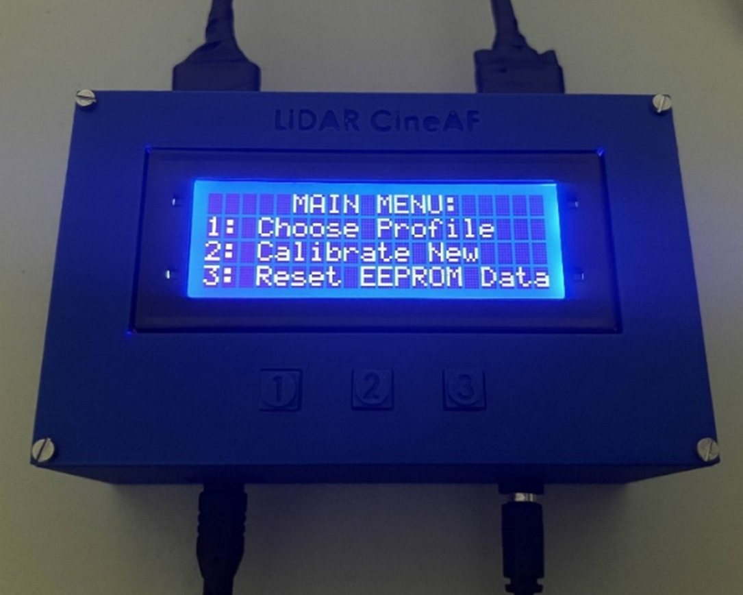
Figure 5: LCD Main Menu, including calibration and profile options.
This information is saved to one of three “profiles” inside the Arduino’s EEPROM memory, so that calibration doesn’t need to be reset each time the device is powered up. Users then have the choice on bootup to select one of these profiles, or to delete all information stored in the EEPROM if the settings need to be recalibrated (see Figure 5). Once a profile has been selected, the system automatically switches into “focusing mode,” during which the autofocusing system is active and adjusts focus, depending on the proximity of an object centered in the frame, while the LCD display reads out a live distance value.
This proof of concept is not 100 percent accurate in all conditions, especially in cases where the system needs to focus through glass or a semi-transparent object and will focus on the distance of the glass instead of the object beyond it. However, in all other cases, the system I built effectively keeps any object in the frame up to 9 meters away in sharp focus and responds quickly to changes in distance and focus, such as when focus needs to quickly change between a background and a subject much closer to the camera, or when the subject is consistently moving.
Project Significance

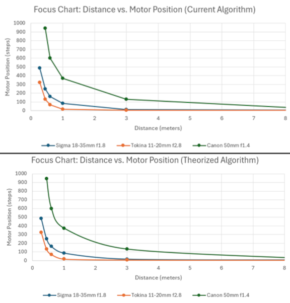
Figure 6: Current Best-Fit Algorithm vs. Theorized Best-Fit Algorithm graphs.
While LiDAR-based autofocus technologies have been readily available in the film industry since the mid- to late 2010s (through products such as the Preston Cinema Systems Light Ranger), these products are meant only for large, multimillion-dollar productions with the funds for expensive camera setups, meaning that they can often range from $5,500 to $6,500 for the sensor alone. This price does not account for the focus gear motor, video interface, or wireless transmission systems, which could total up to $30,000 when combined (Muña, 2024). With the proliferation of low-cost sensors and microcontrollers available now, such a system can be designed for a much lower cost—a niche that has been partially filled by products such as the PDMovie LiveAir 3, which is an all-in-one product that allows for LiDAR-based autofocus at a sub-$500 price (Podolski, 2024). However, the core issue with devices like LiveAir 3 is their very short, single-beam sensor layouts, having a maximum range of only 3–4 meters. The LiDAR-based autofocus device I created is significantly less expensive than the competition (with a total material cost of only $71.69 per unit) and boasts a 9-meter-range single-beam sensor. This makes the system I designed most cost-effective for low-budget filmmakers and provides more functionality for filmmakers and cinematographers to use on-set.
Nevertheless, there are still areas of the system I designed that could be fixed or improved upon for the future development of this project. The usage of more sophisticated LiDAR sensors (specifically LiDAR sensor arrays, which use several individual sensors pointed in different directions) could improve the versatility of the autofocus system through tracking multiple points in the frame as opposed to a single point. The usage of a LiDAR array would also allow for more complex focus tracking systems to be implemented, such as face or body tracking to keep focus constant on a moving subject. In addition, a more natural “curve-extrapolation” algorithm could be used to determine the exact position of the focus gear for each distance measurement. The current algorithm is only an approximation, meaning that there are slight variances in the algorithm that could be fixed with an updated version (see Figure 6). Finally, different materials could be explored for manufacturing the system’s components (including the case design and user interface) to increase the physical reliability and longevity of the system, as well as miniaturizing the case and electronics for convenience and ease of use.
Reflection
This project has been an incredible experience throughout—both in terms of learning research procedures and in developing my path in engineering. While I worked with my project mentor (Dr. Richard Messner) to communicate daily progress and get feedback throughout the summer, I completed much of the planning, design, and troubleshooting independently.
In addition, the project acted as a combination of all the skills that I have learned in engineering up to this point, including electronic design, microcontroller coding, and mechanical assembly. My interests lie in electromechanical design for hardware as it pertains to audio and video technology. My plan is to continue research in this field throughout my academic career as an undergraduate and graduate student. Additionally, being a filmmaking enthusiast for several years, this project acted as a bridge between my passions in and outside of engineering and provided personal fulfillment as well. I am genuinely proud of the final product and my knowledge of a near-endless number of ways to improve upon the system that I designed to make it the very best it can be. For students interested in pursuing research, my best piece of advice is to find a way to tie their personal passions to the work itself. By doing so, the work is often of a higher quality while also retaining the personal spark of what drives one to do better, both in academia and beyond.
I would like to thank everyone at the Hamel Center for Undergraduate Research and the generous financial support from Mr. Dana Hamel—this project simply would have not been possible without their help. I would like to thank Dr. Richard Messner for his invaluable help as my project mentor throughout the entire time span of this project, from proposal to presentation. I would also like to thank all the staff members at the UNH Technical Service Center (TSC), including TSC director Kevan Carpenter, mechanical engineer Noah MacAdam, and senior electronics engineer James Abare for their continuous help with space reservation and equipment usage throughout the summer. Last but not least, I would like to thank my family and friends who have supported my work in research from the very beginning. Without you all, I would not be where I am today.
Works Cited
Muña, Roque. “Preston Cinema Systems—Product Information.” www.prestoncinema.com, 2024, prestoncinema.com/products/product-info/. Accessed 27 Feb. 2024
Podolski, Art. “PDMovie LiveAir 3 Smart—LiDAR AF Follow Focus System in Review.” www.lensvid.com, 16 Jan. 2024, https://lensvid.com/gear/pdmovie-liveair-3-smart/. Accessed 27 Feb. 2024.
All images/figures created by Nolan Juneau.

Author and Mentor Bios
Nolan Juneau will graduate from the University of New Hampshire in May 2026 with a bachelor’s degree in electrical engineering and a minor in mechanical engineering. He is a member of the Hamel Honors and Scholars College in the interdisciplinary track, as well as a member of the UNH student branch of the Institute of Electrical and Electronics Engineers (IEEE). Nolan also serves as a student ambassador for the Hamel Center for Undergraduate Research. Outside of academia, Nolan is the vice president of Wildcat Film Club, and his love of filmmaking and camera technology combined with his work in electrical engineering is what influenced this project’s creation. After graduation, Nolan plans to pursue a doctorate in electrical engineering, relating to his research interests in electronic circuit design and electromechanical systems.
Richard Messner received the B.S. and M.S. degrees from Clarkson College of Technology, Potsdam, New York, in 1979 and 1981 respectively. From 1981 to 1982 Dr. Messner was a member of the technical staff at the MITRE Corporation working on error-correcting codes for the MILSTAR satellite system. In 1982 he received a fellowship and conducted his PhD research in the Applied Optics Branch of the Optical Sciences Division at the Naval Research Laboratory in Washington, D.C., under the direction of Dr. Harold H. Szu. He completed the requirements of the PhD degree from Clarkson University in December 1984. Since January 1985 Dr. Messner has been a faculty member in the Department of Electrical and Computer Engineering at the University of New Hampshire. In addition to teaching, he consults regularly with industry in the areas of optical signal processing, real-time digital image processing, and the development of smart visual sensors. Dr. Messner is a senior member of IEEE, and is a member of SPIE, Eta Kappa Nu, and Life member of Sigma Xi.
Copyright 2025 © Nolan Juneau